Как проектировать кастомные детали из углеродного волокна: гид покупателя
От концепции до серии — практический гид по заказу кастомных карбоновых компонентов у производителя.
Это техническое руководство подготовлено инженерной командой MASTERMATE на основе нашего опыта в выборе материалов из углеволокна, производстве композитов, CNC-обработке и OEM/ODM-производстве.
Большинство первых покупателей кастомных карбоновых деталей приходят с отличной геометрией, но размытым пониманием того, что делает дизайн технологичным. Итог — два-три раунда переписки до котировки. Этот гид — тот же чеклист, через который мы проводим новых клиентов на intake-звонках: форматы файлов, правила толщины стенки, реальность допусков и сигналы, говорим ли мы о формовании, раскладке или просто CNC-фрезеровке плоского листового stock.
Шаг 0 — Определите миссию до геометрии
До любого чертежа напишите абзац «mission statement» для детали. Он должен ответить: что делает деталь, какие нагрузки несёт, в какой среде живёт и какой доминирующий отказ вы предотвращаете? Дизайнеры, пропускающие этот шаг, почти всегда переусложняют не ту ось и недопроектируют опасную [1].
Шаг 1 — Форматы файлов, которые реально нужны производителю
Время котировки сильно зависит от usable файлов. Пришлите правильный формат с первого раза — и вырежете минимум один round-trip из графика [2].
| Тип детали | Лучший формат | Допустимый fallback | Избегать |
|---|---|---|---|
| Плоская пластина / CNC-деталь | DXF (2D) + PDF-чертёж | STEP, IGES | JPG эскиза |
| Формованная 3D-деталь | STEP (AP203/214) | Parasolid (.x_t), IGES | STL (теряет допуски) |
| Труба / pultruded | PDF-чертёж с размерами | STEP | Устное описание |
| Сборка из нескольких деталей | STEP-сборка + PDF BOM | Подетальные STEP | Один combined CAD без exploded BOM |
Всегда прикладывайте 2D PDF рядом с 3D. PDF задаёт допуски, требования к отделке, направление плетения и косметические vs силовые зоны. Без него производитель будет угадывать — и угадка не совпадёт с вашей.
Шаг 2 — Толщина стенки, радиусы и другие жёсткие лимиты
У формования CFRP есть правила технологичности, как у литья под давлением. Их нарушение либо взвинчивает стоимость, либо делает деталь неформоуемой.
| Элемент | Рекомендуется | Минимум | Примечания |
|---|---|---|---|
| Толщина стенки | 1,5–3,0 мм | 0,6 мм | Ниже 0,6 мм число ply падает ниже уровня предсказуемой прочности. |
| Внутренний радиус угла | ≥ 3 × толщина ply | 0,5 мм | Острые внутренние углы дают fiber bridging и лужи смолы. |
| Наружный радиус угла | ≥ 1 × толщина ply | 0,25 мм | Жёстче возможно, но даёт fiber kinking. |
| Расстояние отверстие–кромка | ≥ 2 × диаметр отверстия | 1 × диаметр | Сверление ближе к кромке вызывает расслоение. |
| Угол уклона (формованные бока) | 1–2° | 0° (с разъёмной оснасткой) | Нулевой draft требует более дорогих разъёмных форм. |
| Допуск косметической поверхности | ±0,5 мм | ±0,2 мм | Жёстче ±0,2 мм требует постобработки после формы. |
| Допуск позиции отверстия (CNC) | ±0,1 мм | ±0,05 мм | Достижимо на плоской пластине, дорого на контурных деталях. |
Шаг 3 — Выберите производственный процесс
Разные процессы оптимизируют разное. Матрица решений ниже — та, что мы используем на первом звонке для short-list подхода [3][4].
| Процесс | Лучше для | Типичный объём | Стоимость оснастки | Срок на деталь |
|---|---|---|---|---|
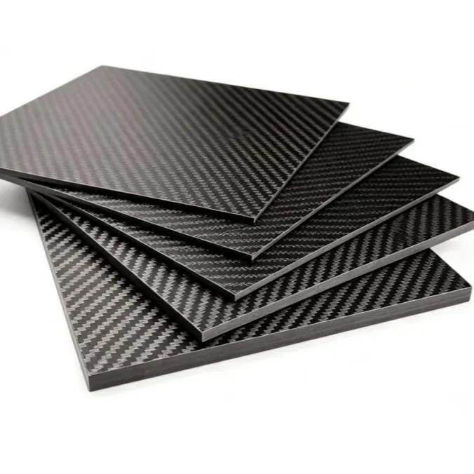
| CNC-фрезеровка (плоская пластина) | Рамы дронов, кронштейны, пластины | 1–10 000 | Нет (листовой stock) | 2–7 дней |
| Ручная раскладка / vacuum bag | Прототипы, малые детали | 1–50 | $200–$1 500 | 5–15 дней |
| Компрессионное формование | Серийные косметические детали | 100–10 000 | $1 500–$8 000 | 7–21 день |
| Resin transfer molding (RTM) | Закрытые силовые детали | 500–50 000 | $5 000–$25 000 | 10–30 дней |
| Автоклавный prepreg | Авиация, мотоспорт | 10–5 000 | $3 000–$30 000 | 14–35 дней |
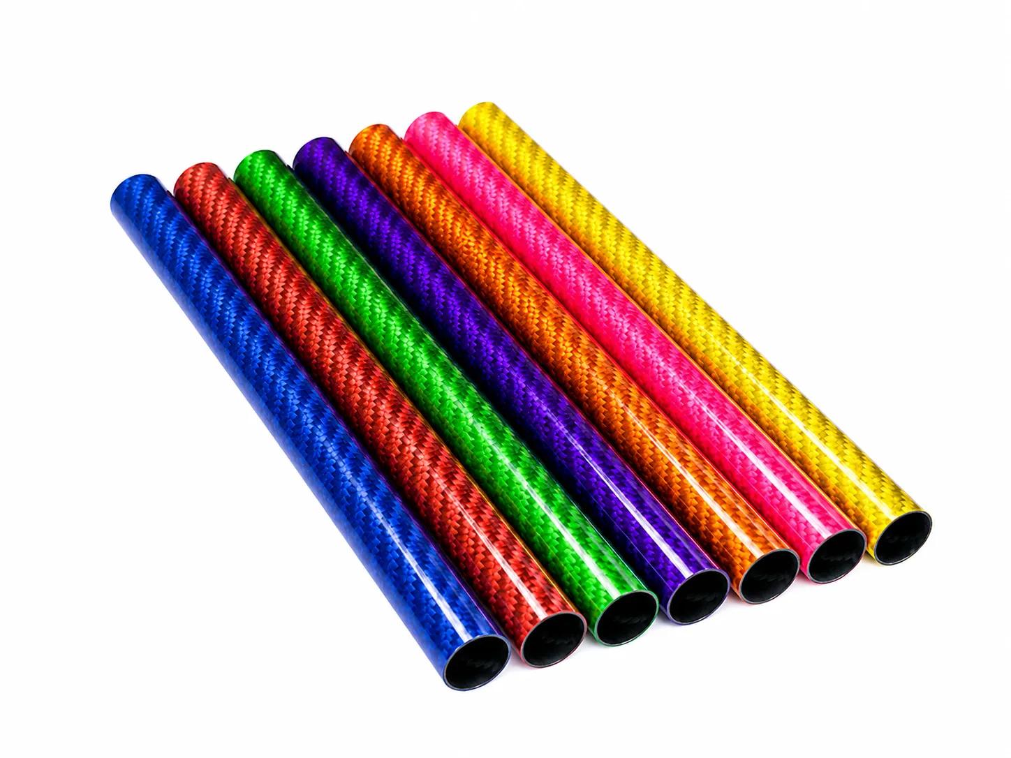
| Намотка нити | Трубы, сосуды давления | 100–100 000 | $2 000–$10 000 | 7–21 день |
Шаг 4 — Стоимость оснастки и точка break-even
Оснастка — главный фактор, удивляющий покупателей. Простая алюминиевая компрессионная форма для косметической панели 200×200 мм — $1 500–$3 000. Сложная многогнездовая стальная для авиационного кронштейна — $15 000–$30 000. Форма — разовая стоимость, но амортизируется только на реально заказанных единицах.
Шаг 5 — Цикл образцов
- 1. Заморозка котировкиУтвердите геометрию, материалы, плетение и допуски. Изменения после этого запускают перекотировку.
- 2. CAM и review toolpathПроизводитель выдаёт CAM-чертежи или раскладки формы. Покупатель утверждает стратегию фиксации.
- 3. Образец T0Первый образец. Покупатель сверяет с чертежом. Большинство проблем ловится здесь и чинится в первой итерации.
- 4. Коррекции T1Корректировка оснастки, геометрии, перерезка. Типичный срок T1 — 5–10 дней.
- 5. Утверждение в стиле PPAPФинальный размерный отчёт, вес, запись ply layup и визуальные фото — письменно до старта серии.
- 6. First-article inspectionВ серии инспектируйте детали 1, N/2 и N, чтобы рано поймать drift оснастки.
Шаг 6 — Допуски без переплаты
Допуск — переменная, которую покупатели чаще всего over-specify. Каждый ужесточающий tier примерно удваивает стоимость инспекции и может учетверить scrap на пределе [5].
| Полоса допуска | Относит. стоимость | Достижимо в | Типичное применение |
|---|---|---|---|
| ±0,5 мм | 1,0× | CNC-пластина, формованная деталь | Большинство потребительских деталей |
| ±0,3 мм | 1,3× | CNC-пластина, постобработанная формованная | Рамы дронов, робототехника |
| ±0,1 мм | 2,5× | CNC-пластина, постобработка | Оптический стол, приборы |
| ±0,05 мм | 4,0× | CNC + lap finish | Авиация, гонки |
| ±0,02 мм | 8,0× | CNC + шлифовка + EDM | Редко, обычно значит металлическая вставка |
Шаг 7 — Чеклист QC, который должен вести поставщик
- Входная верификация материала: номер партии prepreg, срок годности, проверка fiber areal weight.
- Запись раскладки: число ply, ориентация и stacking sequence на деталь.
- Лог цикла отверждения: трасса температуры/давления на партию (автоклав или печь).
- Размерная инспекция: критические размеры штангенциркулем / CMM, полный first-article отчёт.
- Проверка веса: ±5% на косметике, ±2% на силовых.
- Визуал: поверхность, fiber print-through, белые пятна, поры.
- Tap-тест или ультразвук на силовых: ловит расслоение, невидимое с поверхности.
- Coupon tensile / interlaminar shear на высокообъёмных сериях (каждая N‑я партия).
Типичные ошибки, которые стоят реальных денег
- Указывать ±0,05 мм везде вместо только сопрягаемых поверхностей (стоимость ×4).
- Проектировать острый внутренний угол («в стиле 3D‑печати») в формованной детали CFRP — волокна не могут повернуть.
- Просить «как на фото» без указания размера плетения, отделки и ориентации.
- Забывать, что расстояние отверстие–кромка < 2 D вызывает расслоение, особенно под preload крепежа.
- Присылать STL как единственный источник геометрии — STL теряет размерный intent дизайна.
- Пропускать 2D-чертёж, потому что «в 3D-модели всё есть» (нет — допуски живут на чертеже).
Часто задаваемые вопросы
Вопросы, которые нам чаще всего задают первые покупатели кастомного карбона.
Какой минимальный заказ кастомных карбоновых деталей?
Для плоских CNC-деталей MOQ фактически 1 — разница стоимости между 1 и 10 невелика. Для формованных MOQ задаётся break-even оснастки, обычно 50–200 шт. Ниже этого объёма ручная раскладка или ЧПУ обычно бьёт формование по total cost.
Сколько длится цикл от дизайна до поставки?
Типичные графики: котировка 2–5 дней, первый образец 7–15 дней, итерация образца 1–2 недели, затем серия 15–30 дней. Закладывайте 6–10 недель на совершенно новую формованную деталь от kickoff до отгруженных единиц.
Нужны ли инженерные чертежи или достаточно грубого эскиза?
Чертёж с критическими размерами и допусками нужен всегда. Эскиза хватает для очень простых деталей (плоские пластины, трубы), но всё с сопрягаемыми элементами требует нормального PDF рядом с CAD.
Может ли производитель помочь с оптимизацией дизайна?
Хороший поставщик сделает Design for Manufacture (DfM) review бесплатно или за небольшую плату. Отметит проблемы толщины стенки, предложит ориентацию волокон, углы уклона и более лёгкие альтернативы. Относитесь как к партнёрству, а не hand-off.
Как защитить IP при передаче CAD производителю?
Подпишите взаимный NDA до отправки файлов; уважаемые поставщики предлагают его как стандарт. Для чувствительной геометрии сначала watermarked PDF, полный CAD — после NDA. Избегайте поставщиков, отказывающихся подписывать NDA.
В чём разница между 3K twill, 12K twill и forged carbon?
3K twill ткан из жгутов 3 000 филаментов с мелким классическим плетением (около 4×4 мм). 12K — из жгутов 12 000 для более крупного смелого узора. «Forged» carbon — рубленное волокно, спрессованное под теплом, даёт мраморный нетканый вид. Прочность схожа, косметика разная; forged гораздо быстрее формовать для сложных 3D-форм.
Подходит ли кастомный карбон для улицы?
Да, с двумя оговорками: эпоксидные смолы должны быть UV-стабилизированы или с topcoat против желтизны, а любой алюминиевый или стальной крепёж в контакте с карбоном — гальванически изолирован. Правильно отделанные outdoor-изделия CFRP (дроны, marine fittings, детали e-bike) регулярно служат 10+ лет.
Sources & Further Reading
- CMH-17 — Composite Materials Handbook (Volume 3, Materials Usage, Design, and Analysis)
- ASTM D3039 — Tensile Properties of Polymer Matrix Composite Materials
- ASTM D7264 — Flexural Properties of Polymer Matrix Composite Materials
- ASME Y14.5 — Dimensioning and Tolerancing
- ISO 9001 — Quality management systems requirements
- AS9100 — Quality Management System for the Aviation, Space and Defense industry
- Hexcel — Prepreg Technology guide
- Toray — Prepreg overview
- CompositesWorld — Design for Composite Manufacturing
- MIT OpenCourseWare — Mechanics of Composite Materials
- NASA Technical Reports Server — Composite Manufacturing
- ASTM D5687 — Standard Guide for Preparation of Flat Composite Panels with Processing Guidelines for Specimen Preparation
Нужны индивидуальные изделия из углеволокна?
Наша инженерная команда помогает брендам по всему миру разрабатывать OEM-решения из углеволокна с низким MOQ и быстрым прототипированием.
Запросите коммерческое предложение сегодня.