How to Design Custom Carbon Fiber Parts: A Buyer's Guide
From initial concept to production — a practical guide to ordering custom carbon fiber components from a manufacturer.
This technical guide was prepared by the MASTERMATE Engineering Team based on our experience in carbon fiber material selection, composite manufacturing, CNC machining and OEM/ODM production.
Most first-time buyers of custom carbon fiber parts walk into the conversation with a great geometry but a fuzzy idea of what makes a manufacturable design. The result is two or three rounds of back-and-forth before the project even gets quoted. This guide is the same checklist we walk new clients through on intake calls — file formats, wall-thickness rules, tolerance reality checks, and the signals that tell you whether you should be molding, laying up, or just CNC-routing flat plate stock.
Step 0 — Define the Mission Before the Geometry
Before you draw anything, write a one-paragraph "mission statement" for the part. It should answer: what does the part do, what loads does it carry, what environment does it live in, and what is the dominant failure you are trying to prevent? Designers who skip this step almost always over-engineer the wrong axis and under-engineer the dangerous one [1].
Step 1 — File Formats Your Manufacturer Actually Wants
Quoting time is a strong function of how usable your design files are. Send the right format the first time and you cut at least one round-trip out of the schedule [2].
| Part type | Best file format | Acceptable fallback | Avoid |
|---|---|---|---|
| Flat plate / CNC-cut part | DXF (2D) + PDF drawing | STEP, IGES | JPG of a sketch |
| Molded 3D part | STEP (AP203/214) | Parasolid (.x_t), IGES | STL (loses tolerances) |
| Tubular / pultruded part | PDF drawing with dims | STEP | Verbal description |
| Assembly with multiple parts | STEP assembly + PDF BOM | Per-part STEP files | A single combined CAD without exploded BOM |
Always include a 2D PDF drawing alongside the 3D file. The PDF defines tolerances, surface finish requirements, weave direction, and any cosmetic-vs-structural areas. Without it, the manufacturer will guess — and their guess will not match yours.
Step 2 — Wall Thickness, Radii, and Other Hard Limits
CFRP molding has manufacturability rules just like injection molding does. Violating them either drives cost up or makes the part outright unmoldable.
| Feature | Recommended | Minimum | Notes |
|---|---|---|---|
| Wall thickness | 1.5–3.0 mm | 0.6 mm | Below 0.6 mm, ply count drops below the level needed for predictable strength. |
| Inside corner radius | ≥ 3 × ply thickness | 0.5 mm | Sharp inside corners cause fiber bridging and resin pools. |
| Outside corner radius | ≥ 1 × ply thickness | 0.25 mm | Tighter is possible but sees fiber kinking. |
| Hole-to-edge distance | ≥ 2 × hole diameter | 1 × diameter | Drilling closer to the edge causes delamination. |
| Draft angle (molded sides) | 1–2° | 0° (with split tooling) | Zero draft requires more expensive split molds. |
| Cosmetic surface tolerance | ±0.5 mm | ±0.2 mm | Tighter than ±0.2 mm requires post-mold machining. |
| Hole position tolerance (CNC) | ±0.1 mm | ±0.05 mm | Achievable on flat plate, expensive on contoured parts. |
Step 3 — Pick a Manufacturing Process
Different processes optimize for different things. The decision matrix below is what we use during the first call to short-list the right approach [3][4].
| Process | Best for | Typical volume | Tooling cost | Per-part lead time |
|---|---|---|---|---|
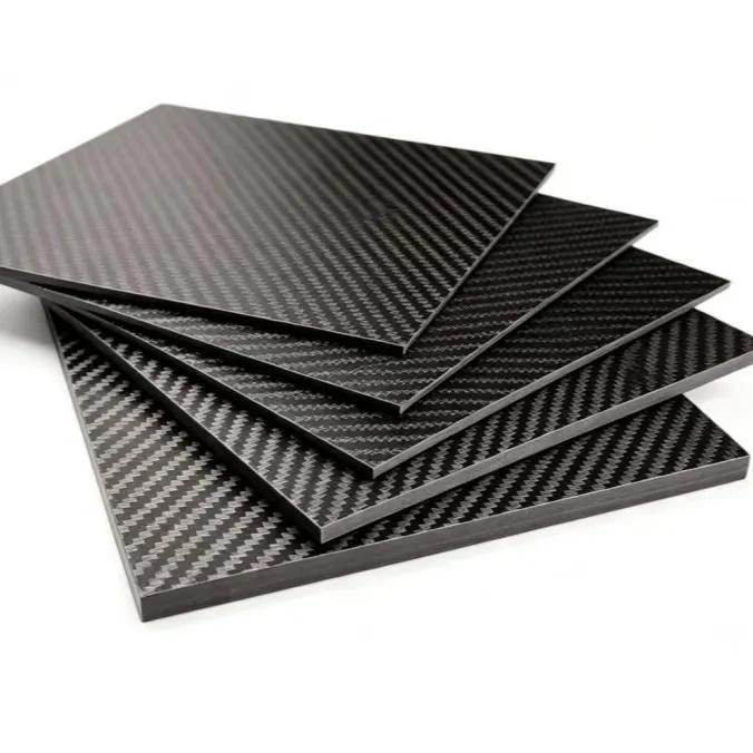
| CNC routing (flat plate) | Drone frames, brackets, plates | 1–10,000 | None (sheet stock) | 2–7 days |
| Hand layup / vacuum bag | Prototypes, small parts | 1–50 | $200–$1,500 | 5–15 days |
| Compression molding | Volume cosmetic parts | 100–10,000 | $1,500–$8,000 | 7–21 days |
| Resin transfer molding (RTM) | Closed structural parts | 500–50,000 | $5,000–$25,000 | 10–30 days |
| Autoclave prepreg | Aerospace, motorsport | 10–5,000 | $3,000–$30,000 | 14–35 days |
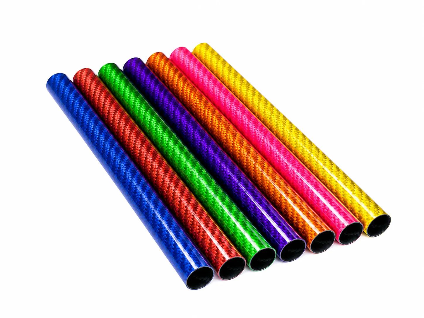
| Filament winding | Tubes, pressure vessels | 100–100,000 | $2,000–$10,000 | 7–21 days |
Step 4 — Tooling Costs and the Break-Even Point
Tooling is the single biggest factor that surprises buyers. A simple aluminum compression mold for a 200 × 200 mm cosmetic panel runs $1,500–$3,000. A complex multi-cavity steel mold for an aerospace bracket runs $15,000–$30,000. The mold is a one-time cost, but you only get to amortize it over the units you actually order.
Step 5 — The Sampling Loop
- 1. Quote freezeSign off on geometry, materials, weave, and tolerances. Changes after this point trigger re-quote.
- 2. CAM & tool path reviewManufacturer issues CAM drawings or mold layouts. Buyer signs off on fixturing strategy.
- 3. T0 sampleFirst sample produced. Buyer inspects against drawing. Most issues caught here are fixable in the first iteration.
- 4. T1 correctionsAdjust tooling, fix any geometry mismatches, re-cut. Typical T1 lead time is 5–10 days.
- 5. PPAP-style approvalFinal dimensional report, weight, ply layup record, and visual photos signed off in writing before mass production starts.
- 6. First-article inspectionIn production, inspect parts 1, N/2, and N to catch tooling drift early.
Step 6 — Specifying Tolerances Without Overpaying
Tolerance is the variable buyers most often over-specify. Each tightening tier roughly doubles inspection cost and can quadruple scrap rate at the limit [5].
| Tolerance band | Relative cost | Achievable in | Common use |
|---|---|---|---|
| ±0.5 mm | 1.0× | CNC-cut plate, molded part | Most consumer parts |
| ±0.3 mm | 1.3× | CNC-cut plate, post-machined molded | Drone, robotics frames |
| ±0.1 mm | 2.5× | CNC-cut plate, post-machined | Optical bench, instrument |
| ±0.05 mm | 4.0× | CNC + lap finish | Aerospace, racing |
| ±0.02 mm | 8.0× | CNC + grinding + EDM | Rare, usually means metal insert |
Step 7 — The QC Checklist Your Supplier Should Be Running
- Incoming material verification: prepreg lot number, expiry date, fiber-areal-weight check.
- Layup record: ply count, orientation, and stacking sequence captured per part.
- Cure cycle log: temperature/pressure trace for each batch (autoclave or oven).
- Dimensional inspection: critical dims with calipers / CMM, full first-article report.
- Weight check: ±5% on cosmetic parts, ±2% on structural.
- Visual inspection: surface, fiber print-through, white spots, voids.
- Tap test or ultrasonic on structural parts: detects delamination invisible on the surface.
- Tensile / interlaminar shear coupons for high-volume runs (every Nth batch).
Common Mistakes That Cost Real Money
- Specifying ±0.05 mm everywhere instead of only on mating surfaces (drives cost up 4×).
- Designing a sharp inside corner ("3D-printed-style") in a molded CFRP part — fibers cannot make the turn.
- Asking for "just like in the photo" without specifying weave size, finish, and orientation.
- Forgetting that hole-to-edge distance < 2 D causes delamination, especially under fastener pre-load.
- Sending an STL file as the only geometry source — STL drops the dimensional intent of the design.
- Skipping the 2D drawing because "the 3D model has everything" (it does not — tolerances live on the drawing).
Frequently Asked Questions
The questions we are asked most often by first-time buyers of custom carbon fiber.
What's the minimum order quantity for custom carbon fiber parts?
For CNC-cut flat parts, MOQ is effectively 1 — the cost difference between 1 and 10 pieces is small. For molded parts, MOQ is set by tooling break-even, typically 50–200 pieces. Below that volume, hand layup or CNC machining usually beats molding on total cost.
How long does the design-to-delivery cycle take?
Typical schedules: 2–5 days quote, 7–15 days for the first sample, 1–2 weeks for sample iteration, then 15–30 days mass production. Plan on 6–10 weeks for a brand-new molded part going from kickoff to delivered units.
Do I need to provide engineering drawings, or can I send just a rough sketch?
You always need a drawing showing critical dimensions and tolerances. A sketch is enough for very simple parts (flat plates, tubes), but anything with mating features needs a proper PDF drawing alongside the CAD model.
Can the manufacturer help with design optimization?
A good supplier will do a Design for Manufacture (DfM) review for free or for a small fee. They will flag wall-thickness issues, suggest fiber orientation, recommend draft angles, and propose lighter-weight alternatives. Treat this as a partnership, not a hand-off.
How do I protect my IP when sharing CAD files with a manufacturer?
Sign a mutual NDA before sending files; reputable suppliers offer one as standard. For sensitive geometries, send watermarked PDFs first and the full CAD only after the NDA is in place. Avoid suppliers who refuse to sign an NDA.
What's the difference between 3K twill, 12K twill, and forged carbon?
3K twill is woven from 3,000-filament tows with a fine, classic weave (about 4 mm × 4 mm pattern). 12K is woven from 12,000-filament tows for a larger, bolder pattern. "Forged" carbon is chopped fiber compressed under heat, giving a marbled, non-woven look. They have similar strength but different cosmetics, and forged is much faster to mold for complex 3D shapes.
Is custom carbon fiber suitable for outdoor use?
Yes, with two caveats: epoxy resins must be UV-stabilized or top-coated to prevent yellowing, and any aluminum or steel hardware in contact with the carbon must be galvanically isolated. Properly finished CFRP outdoor products (drones, marine fittings, e-bike parts) routinely last 10+ years.
Sources & Further Reading
- CMH-17 — Composite Materials Handbook (Volume 3, Materials Usage, Design, and Analysis)
- ASTM D3039 — Tensile Properties of Polymer Matrix Composite Materials
- ASTM D7264 — Flexural Properties of Polymer Matrix Composite Materials
- ASME Y14.5 — Dimensioning and Tolerancing
- ISO 9001 — Quality management systems requirements
- AS9100 — Quality Management System for the Aviation, Space and Defense industry
- Hexcel — Prepreg Technology guide
- Toray — Prepreg overview
- CompositesWorld — Design for Composite Manufacturing
- MIT OpenCourseWare — Mechanics of Composite Materials
- NASA Technical Reports Server — Composite Manufacturing
- ASTM D5687 — Standard Guide for Preparation of Flat Composite Panels with Processing Guidelines for Specimen Preparation
Need Custom Carbon Fiber Products?
Our engineering team helps brands worldwide develop OEM carbon fiber solutions with low MOQs and rapid prototyping.
Request a Quote Today.