FPV Frame Build Guide: Arm Thickness, CNC Holes & Layup
Geometry, edge distance, UD vs twill arms, and factory CNC tips — the checklist before you cut a carbon FPV frame.
This technical guide was prepared by the MASTERMATE Engineering Team based on our experience in carbon fiber material selection, composite manufacturing, CNC machining and OEM/ODM production.
This guide is the practical companion to our materials article — it skips the "why carbon" question and goes straight to the geometry, layup, and assembly decisions that turn a sheet of CFRP into a flight-worthy frame. If you are about to lay out your first FPV build or scale a small frame brand into production, every section below is a checkpoint worth walking through before any chips fly.
Geometry First: Motor-to-Motor and Stack Layout
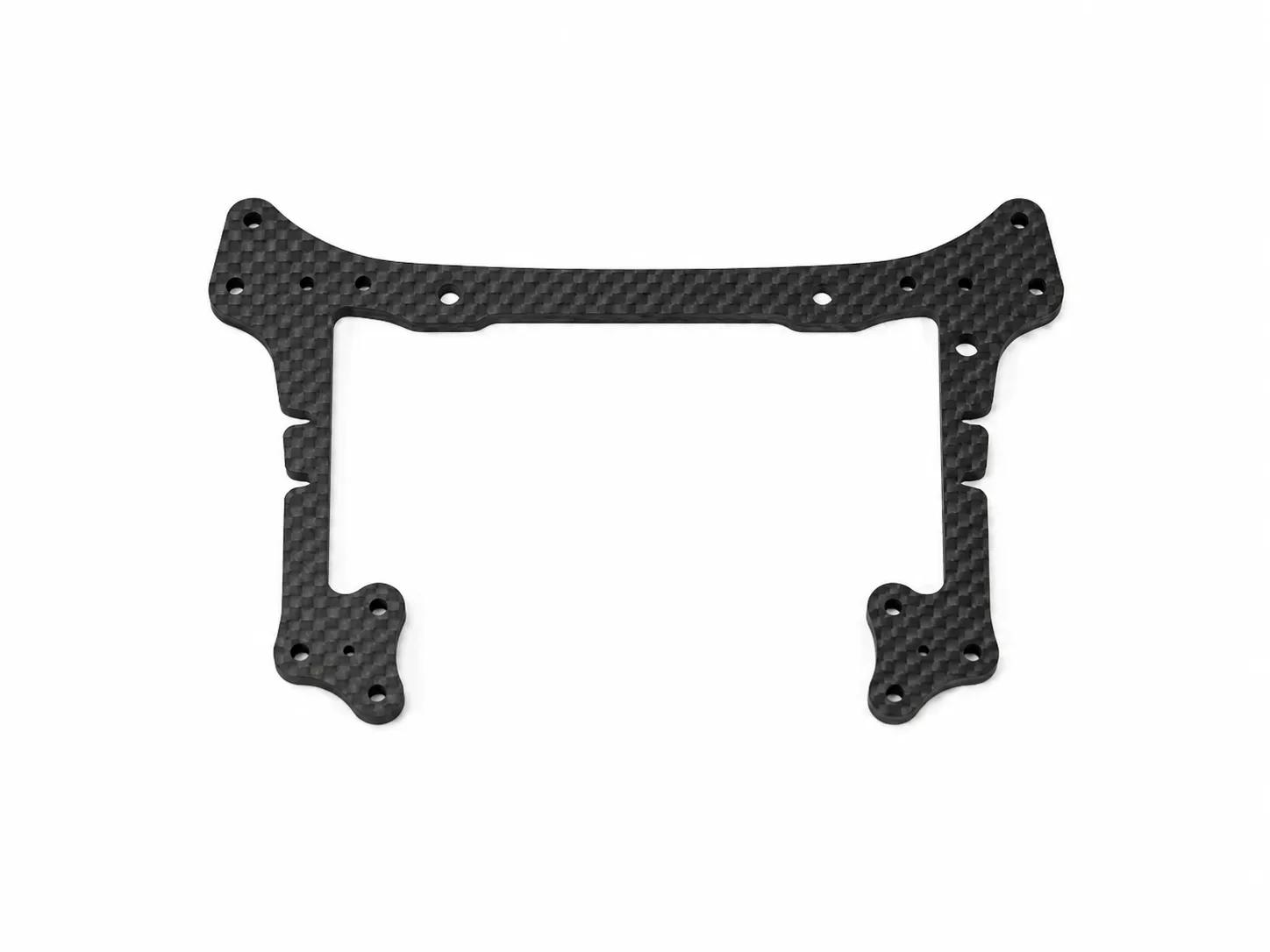
Frame design starts with two numbers: the motor-to-motor diagonal (which determines prop size) and the stack height (which constrains your flight controller, ESC, and VTX choice). Get these wrong and the build is unfixable; get them right and the rest is just CNC tweaks [1].
| Class | Motor-to-motor | Prop size | Typical use |
|---|---|---|---|
| Tinywhoop | 60–85 mm | 31–40 mm (ducted) | Indoor cruise, beginner |
| Toothpick | 110–150 mm | 2.5–3.5 inch | Indoor / light outdoor |
| CineWhoop | 160–200 mm (ducted) | 2.5–3 inch (ducted) | Cinematic indoor |
| 5-inch racing | 210–225 mm | 5 inch | Race + freestyle |
| Long-range | 260–315 mm | 6–7 inch | Cruise, FPV exploration |
| Cinelifter | 350–500 mm | 8–10 inch | Pro cinematography (RED, BMPCC payload) |
Arm Design: Where Layups Earn Their Keep
Arms see the highest cyclic loads on a quad. Pure twill plate works, but unidirectional layups along the load axis can drop arm weight 25–30% at equivalent stiffness. The trade-off is a more brittle response to side impacts — fine for racing arms, less ideal for freestyle that takes hits from every direction.
Mounting Holes, Standoffs, and the Quiet Killer
Carbon plates fail at holes, not in the open. The single most common DIY mistake is drilling a 4 mm hole 4 mm from the plate edge — too close, and the laminate delaminates around the fastener under any side load [2].
- Always chamfer or counter-sink hole entries — sharp edges concentrate stress and can craze the topcoat.
- Use M3 nylon insert lock-nuts on motor mounts. Standard nylocks loosen under vibration after ~50 flight packs.
- For permanent stack assemblies, a drop of medium-strength threadlocker (Loctite 243) on every screw saves hours of in-flight surprises.
- If you are using captive nuts, glue them in with epoxy — pressed-fit nuts walk loose under cyclic loads.
Weight Budget: Where Every Gram Goes
A pro-level 5-inch racing build comes in at ~480 g all-up weight (AUW) with battery. Knowing how that breaks down helps you decide where to optimize first.
| Component | Weight | Optimization potential |
|---|---|---|
| Frame (CFRP) | 95–110 g | Switch to UD arms (-15 g) |
| 4× motors | 110–140 g | Smaller stator (-20 g, costs power) |
| Flight controller / ESC stack | 15–25 g | AIO board (-5 g) |
| VTX + antenna | 6–14 g | Small fixed-power VTX (-5 g) |
| Camera + mount | 10–18 g | DJI O3 air unit (+12 g but worth it) |
| 4× propellers | 12–18 g | Tri-blade vs. five-blade |
| Receiver | 0.5–3 g | Negligible |
| Battery (4S 1300 mAh) | 160–185 g | Single cell choice dominates flight time |
Assembly Sequence: The 30-Minute Checklist
- 1. Inspect every plateHold under a lamp. Look for delamination at edges, missed cuts at hole positions, surface cracks. Reject any defect — easier than removing the bad plate later.
- 2. Seal cut edgesThin CA glue along every CNC-cut edge. This blocks moisture wicking and stops fiber tear-out from progressing.
- 3. Dry-fit standoffsConfirm hole alignment top-to-bottom. Tap any tight holes with the right reamer before forcing a screw through.
- 4. Mount motors with threadlockerLoctite 243 or equivalent. Torque to motor manufacturer spec — typically 1.5–2.5 Nm for M3.
- 5. Solder ESC and FC, then plug in stackTest power-up before stack tightening. It is way easier to fix a soldering error before the frame is buttoned up.
- 6. Pre-flight: gentle press test on each armHand-load each arm tip ~1 kg. Listen for cracking. Better to find a flaw on the bench than at altitude.
Frame Stiffness and PID Tuning Are Linked
A frame that flexes during punch-outs introduces phase lag into the gyro signal — your tune fights the airframe instead of the air. Two warning signs that frame stiffness is the problem and not your PIDs: (1) prop-wash handling is fine but rolls feel "squishy" above 80% throttle, (2) gyro noise spikes correlate with throttle position rather than RPM. Fix the frame before re-tuning [3].
Scaling Up: From 10 Frames to 10,000
Most frame brands start by hand-cutting 10 prototypes on a hobby CNC. The economics change quickly with volume — at 100+ frames, batched stack-cutting on a production machine drops per-frame labor below $5. At 1,000+ frames, fixturing investment is amortized in the first run. Compression molding only enters the math above ~5,000 frames per design.
Frequently Asked Questions
Practical questions from builders going from one prototype to a small production run.
How tight should I torque M3 stack screws on a CFRP frame?
1.0–1.5 Nm for stack-internal screws (FC/ESC/standoffs), 1.5–2.5 Nm for motor mounts. Over-torquing crushes the laminate around the hole and weakens it permanently.
Can I drill new holes into an existing frame?
Only with a sharp diamond-coated drill, masking tape on both faces, and a backing block. Always chamfer the exit hole. Make sure the new hole respects the 2× edge-distance rule. If in doubt, send the design back to your manufacturer for re-cut.
Why do some pilots epoxy-coat their CNC plates?
A thin epoxy seal across the surface (not just edges) hides the cosmetic effects of micro-scratches and slows UV degradation. It adds 2–4 g per frame and is purely optional — most race-class frames ship without it.
What's the safe minimum thickness for a 5-inch arm?
4 mm in T700 layup is the realistic minimum for race-grade abuse. 3 mm arms exist but routinely snap on hard contact. For freestyle, 5 mm is the standard.
Can I use a desktop laser cutter on carbon fiber?
No. Laser cutting CFRP releases hazardous gases (HCN among others) and leaves a charred resin edge that is structurally weaker. Use a CNC router with diamond tooling and proper dust extraction.
How do I prevent vibration from loosening fasteners over a season?
Loctite 243 (medium-strength) on all stack and motor screws is the standard preventive. Combined with nylon insert lock-nuts on motor mounts, you should not need to re-torque between rebuilds.
Sources & Further Reading
- Wikipedia — Aircraft fasteners and edge-distance rules
- NASA Composite Materials Handbook (CMH-17)
- OSHA — Carbon fiber dust handling guidance
- NIOSH — Respiratory protection for composite machining
- Loctite 243 product datasheet
- Toray — Composite Materials prepreg systems
- Betaflight documentation (gyro filtering and PID basics)
- FAI — UAV / FPV racing class regulations
- ASTM D5379 — Iosipescu shear test for composites
- Hexcel — Prepreg processing handbook
- Cyanoacrylate adhesives — properties and edge sealing applications
- CompositesWorld — CNC machining of CFRP
Need Custom Carbon Fiber Products?
Our engineering team helps brands worldwide develop OEM carbon fiber solutions with low MOQs and rapid prototyping.
Request a Quote Today.