Carbon Fiber CNC Machining: Design Rules, Holes and Tolerances
Design-for-machining rules for carbon fiber parts: cut edges, hole placement, delamination, fixturing and what a drawing must define before CNC.
This is the machining briefing MASTERMATE uses before quoting a cut carbon fiber plate or bracket. It is process guidance, not a measured tolerance for a named part.
Laminate stiffness still comes from the ply schedule. Set that in the laminate design guide before you spend tolerance budget on a hole. Broader geometry rules sit in how to design custom carbon fiber parts.
1. Choose CNC for plate geometry, not for every shape
CNC trimming and drilling suit flat or gently contoured cured laminates: plates, brackets, spacers and frames cut from sheet. Deep 3D shells, continuous fibers wrapped around a curve, and parts whose strength depends on an unbroken molded surface are usually a molding problem. Cutting those fibers to create the shape is a different design. Say which one you need in the RFQ so the process is not guessed from a render.
2. Holes fail by delamination more often than by diameter
Carbon plies are strong in the fiber direction and easy to split between plies. As a drill breaks through, the last plies can lift instead of cut. That push-out delamination is the defect composite drilling guides focus on; peel-up can also occur where the tool enters [1]. A sacrificial backing plate, a sharp tool made for composites, and a feed that does not dwell on the exit all address that mechanism. They do not, by themselves, guarantee a diameter.
| Choice | Why it matters |
|---|---|
| Edge distance | A hole too close to a free edge leaves a narrow ligament that splits along the fibers |
| Backing or stack support | Supports the exit ply so the drill cuts it instead of lifting it |
| Countersink | Removes outer plies locally; call it out instead of assuming a metal countersink depth |
| Ply axis on the drawing | The weak direction of the laminate decides where a crack wants to run |
3. Do not copy a metal tolerance onto a laminate
Cured laminate thickness varies with resin content and cure. A drilled diameter also moves as the tool wears and as the material springs back. Publishing a universal shop tolerance, in millimetres or microns, would overstate what a drawing can demand. Ask for the critical dimensions only, inspect those on a production-intent sample, and write the acceptance method into the order. General metal tolerance systems are not a carbon-fiber material specification.
4. What the file should contain
- STEP for the solid, or DXF for a flat profile, with units.
- A datum scheme and the dimensions that are critical to fit.
- Finished thickness, or the stock plate you are willing to accept.
- The 0° fiber direction relative to an edge.
- Hole diameters, countersinks and the minimum edge distance you need.
- Quantity and whether the first articles are for fit only or for a measured approval.
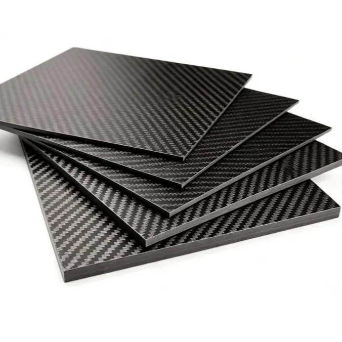
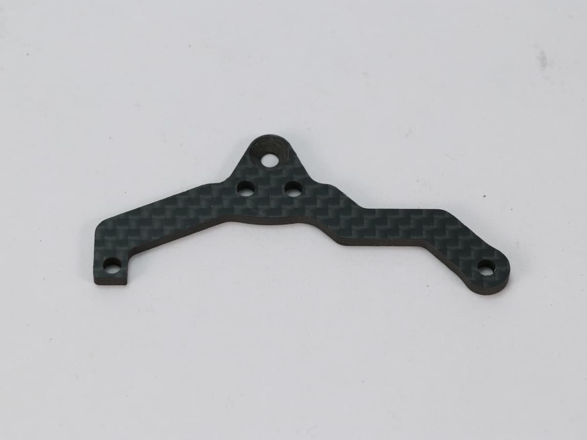
Request the quote on custom carbon fiber parts. CNC-ready carbon fiber plate is the stock form this process usually starts from. A custom CNC-cut part shows the kind of outline machining this article describes; your file still sets the laminate and the tolerances.
Can every carbon fiber hole hold a ±0.05 mm tolerance?
No. Hole size depends on the laminate, tool condition, backing and feed. Agree the critical dimensions on a sample instead of copying a metal-shop tolerance onto the drawing [1].
Why do drilled carbon fiber holes chip on the back face?
The last plies can lift as the drill exits. That push-out delamination is reduced by supporting the exit face and using a sharp composite drill, not by diameter tolerance alone [1].
Should a 3D shell be CNC-cut from plate?
Only if the design really is a machined plate or a trimmed laminate. A shape that needs continuous fibers around a curve is a molding question. Say which geometry you have in the RFQ.
Sources & Further Reading
How This Guide Was Prepared
Delamination and tool guidance follow published composite-machining practice, including Sandvik Coromant’s composite drilling notes. No hole tolerance, edge chip size or cycle time in this article is a MASTERMATE inspection result.
Need Custom Carbon Fiber Products?
Our engineering team helps brands worldwide develop OEM carbon fiber solutions with low MOQs and rapid prototyping.
Request a Quote Today.